What Is Mach Number ?

In fluid mechanics, the Mach number is the ratio of the velocity of a moving mass to the speed of sound in the case of the mass. Its abbreviation is Ma or M. It is named after the Austrian physicist and philosopher Ernst Mach. It is also called the Sarrau number from the studies made by the French physicist Sarrau on this subject before Ernst Mach.

\mathrm {M} ={\frac {u}{c}}

The local sound velocity and the Mach number around it are relative to the course of the ambient gases. Mach, first of all. used to be used in a way that is impractically illegible. This medium can be gas or a room. The boundary layer can move through the medium, or move at constant speeds as it flows through the medium, or both at different speeds: performance is at relative speeds that matters. This is the simulation of a channeling tunnel or center of a constrained, possible integrated object. The Mach number is a quantity of dimensions that can be defined as the ratio of two speeds. Mach numbers less than 0.2-0.3 and fully constant and isothermal, reducibility can be applied and simplified non-scalables can be used.

The airway falls from the ground up. The layers of the atmosphere with sea indicators up to 11 km high (as much as the number of Stratosphere) are called the troposphere. From the square of the speed of sound, from the users in the right way with the air, from the speed of sound as it rises. Accordingly, the number of heights is less than the mach sea view.

Mach Sayısı | Ucaklar.org ✈️
Ses Hızı ve Mach Sayısı Nedir ? Ses Hızı Kaçtır ? | Mühendistan

Importance of Mach Number

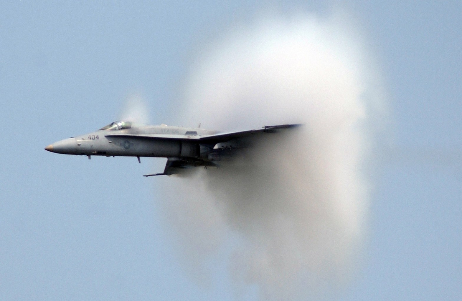
First of all, the Mach number gives information about the flow regime. If the Mach number is less than one, it is called subsonic, if it is equal to one, it is called fast (sonic), if it is greater than one, it is called supersonic. It also indicates that the flow is compressible or incompressible as we mentioned before. If M<0.3, the flow is considered incompressible and the density is taken as constant in aerodynamic calculations. On the other hand, when M > 0.3, the flow is said to be compressible.

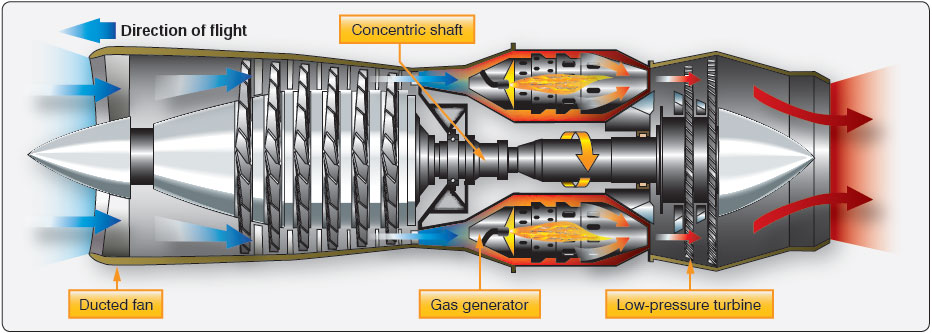
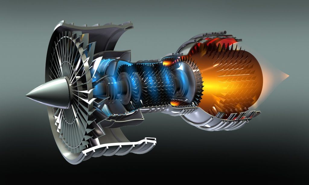
In the aerodynamic calculations for the compressible and isentropic flow of a calorically perfect fluid, other flow properties can be easily calculated if one of the properties of the flow and the Mach number are known, thanks to the isentropic equations. For example, as shown in the formula below, if the temperature of the fluid at one point and the Mach number are known, the total temperature can be calculated as well as its properties at different points in the flow. These calculations are used in many areas such as the analysis of isentropic regions of the internal flow of a jet engine, especially shock waves.

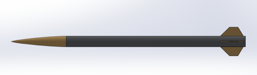
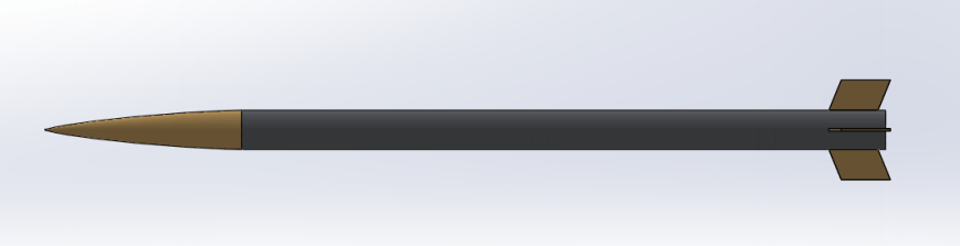
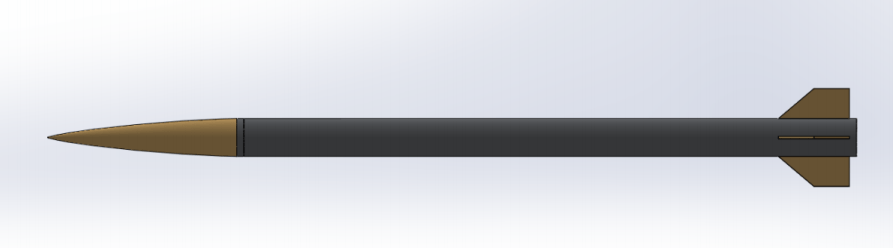
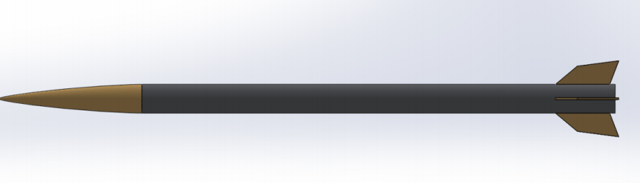
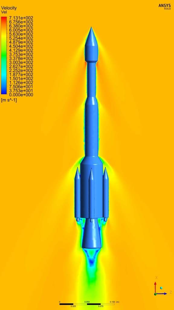
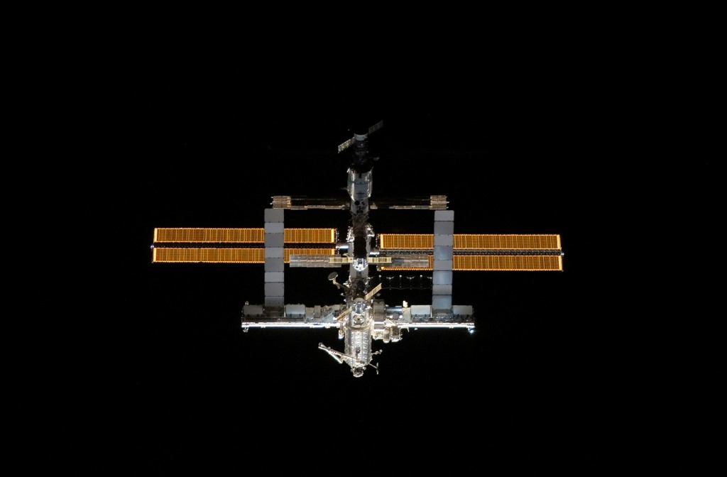
In rocketry calculations and analyses, the mach number tells the awls the conditions we must consider regarding our design. The design suitable for each mach number area makes different requirements essential.

Stay with science and knowledge.

Halit Yusuf Genç

Sources:

Wikipedia

Pixabay

Ucaklar.org

Correct Fin Shape Selection For High Altitude Rockets With A Simple Example

This research is presented to you simply as a brief explanation of a small part of the detailed analysis we have done for the PARS Rocket Group. The main aim of our research is to determine the appropriate shapes from the 4 different fin types we have with the help of computational fluid mechanics (CFD).

Solidworks drawings of our fin geometries are as follows:

Trapezoidal
Parallelogram
Upright Trapezoidal
Special Design

In normal analyzes, 2D analyzes are performed as the first step. The fins that are successful in 2D analysis are considered suitable for moving to 3D analyses.

In these 2D analyzes we made, the wing that managed to reach the highest altitude was the specially designed wing, while the winglet that remained at the lowest altitude was the trapezoidal wing.

If such a choice had been made without including CFD, that is, 3D analysis, and the fin had been directly selected with these 2D analyses, a big mistake would have been made. You ask why ? Let’s examine the reason together.

Our 3D-CFD analysis results are listed below. Let’s first interpret the analyzes starting from the speed contours:

Trapezoidal Fin Velocity Contour
Parallelogram Fin Velocity Contour
Upright Trapezoidal Fin Velocity Contour
Special Design Fin Velocity Contour

Speed contours show us whether there is a deterioration in the outflow of rockets. There is no separation of flow in any of our examples. So the fins are suitable for use. However, the first thing that catches our attention in the design of the fins is the pointed tip on the leading edge. Due to the pointed design of this tip, an acceleration has occurred on the leading edge of the winglet. This is undesirable, so that corner should be rounded in all our fins and the fins should be designed that way. However, since this is a simple analysis, we can ignore this error for now. If this error is ignored, there is no other problem with the fins.

Now it’s time for the pressure contours and our choice of suitable fins will start to take shape at this point.

Trapezoidal Fin Pressure Contour
Parallelogram Fin Pressure Contour
Upright Trapezoidal Fin Pressure Contour
Special Design Fin Pressure Contour

When these pressure contours are considered and the numerical pressure values are compared, it is clearly seen that the parallelogram and the specially designed fin are not suitable designs for our rocket. So why ?

Problems for parallelogram fin:

When we look at the parallelogram fin, we see a serious increase in pressure, not a decrease in pressure. We see a dark red and high numerical value pressure on the fin edge, which is short and first exposed to the flow, called the leading edge. While the pressure in other fins is less than 2.5 kPa, the pressure in this fin reaches up to 4 kPa. Moreover, this numerical value is the pressure on the reduced and modeled version of the rocket. In an analysis on real designs, this pressure difference between the other fins and the parallelogram fin will appear as a larger value. This fin type should not be preferred in case the fin is not damaged by these pressures caused by heat and strength, and against adverse situations such as crashing, exposure to loss of stability, and burning that may occur with this damage.

Problems for special design fin:

Although this fin type was our highest altitude wing on 2D analysis, it showed the opposite result in our aerodynamic analyzes. When the pressure contour is looked at carefully, it can be seen that there is a serious pressure drop at the rear of the fin. These negative pressures indicate that our rocket may be subject to obvious turbulence, and it is normal for it to wobble during flight. This is an undesirable situation for a stable flight. The flight of the rocket will not be healthy. Therefore, it is not a suitable design.

Upright Trapezoidal (Crooked) Fin and Its Basic Problems:

There is no problem due to pressure or flow separation in the trapezoidal blade. The design is aerodynamically appropriate. The only downside to this fin is its large surface area compared to other options. However, in addition to this size, production is also easier compared to others.

Trapezoidal Fin and Its Basic Problems:

As with the trapezoidal fin, no aerodynamic problems were observed in this fin. In addition, since the surface area of the fin is smaller than the vertical trapezoidal shape, it will also be affected by the friction force at a minimum level, so it is the design type that should be preferred for a good altitude. The only downside is that it needs a good mechanical design. As long as the production and assembly is done correctly, the abandonment of high-altitude rocket teams like us will undoubtedly be trapezoidal fin type.

Pars Roket – Daima ileriye!
PARS Rocket Group- ATA-2 Rocket

In other words, trapezoidal and upright trapezoidal (crooked) shapes are suitable aerodynamically designed shapes, whereas parallelogram and special design fins are not suitable aerodynamically. To reach these conclusions; Check if there is any pressure on the vane that could cause turbulence or serious damage over the pressure contours. On the velocity contour, it should be checked whether there is separation in the flow, that is, whether the flow analysis and the flight of the assumed design are smooth.

Stay with science and knowledge.

Halit Yusuf Genç

PARS Rocket Group Aerodynamic Member

Brief Introduction to CFD Analysis

As science began to classify the natural dynamics and related reactions of air, water, or gas, the physics of fluid dynamics continued to develop. This provides a system structure with rules of thumb and is derived from the idea of ​​flow measurement to solve practical problems. Typical fluid dynamics problems involve basic fluid properties related to time and space, such as flow rate, pressure, density, and temperature.

In daily life, we can find fluid flow in meteorology (rain, wind, flood, hurricane), heating, ventilation and air conditioning, aerodynamic design, engine combustion, industrial processes or the human body—for example, blood flow-. Fluid dynamics has a wide range of applications, including calculating forces on airplanes, determining the mass flow of oil through pipelines, and predicting weather patterns.

The flow behavior of gases and liquids is quantified by partial differential equations, which represent the laws of conservation of mass, momentum, and energy. Computational fluid dynamics (CFD) is a branch of fluid mechanics that uses numerical analysis and algorithms to solve fluid flow conditions. Use a high-performance computer to perform the required calculations to simulate the interaction of liquids and gases with surfaces defined by boundary conditions.

The CFD software is based on the Navier-Stokes equation. Since Newton’s second law is applied to fluid motion, coupled with the assumption that the stress in the fluid is the sum of the diffusion viscosity term and the pressure term, these equations describe the velocity, pressure, temperature, and density of the moving fluid.
The development of CFD and the increase of CFD software applications are closely related to the development of high-speed computers.

With a CFD analysis, we can understand the flow and heat transfer throughout the design process. The basic methodology for any engineering CFD software analysis is based on a few procedures:


• Understanding flow model — Flow separations, transient effect, physical interactions;
• Proving assumed model — Experimental results validation, parametric studies, structural simulations;
• Model optimizing — Reducing pressure drops, flow homogenization, improving laminar and turbulent mixing.

Without numerical simulations of fluid flow, it is very difficult to imagine how:


• Meteorologists can forecast the weather and warn of natural disasters;
• Vehicle designers can improve aerodynamic characteristics;
• Architects can design energy-saving and safe-living environments;
• Oil and gas engineers can design and maintain optimal pipes networks;
• Doctors can prevent and cure arterial diseases by computational hemodynamic.

So we can say with certainty that CFD analysis is very critical in many areas such as engineering, weather, R&D, medicine. The profession of CFD analyst, which has now become a specialized field, also receives high salaries in many parts of the world. This is an indication of the need for them.

Stay with science and knowledge.

Halit Yusuf Genç

Sources:

http://www.simscale.com

What Is Jet Engines And How Does It Works

A jet engine is a machine that converts energy, rich liquid fuel into a powerful thrust called thrust. The thrust of one or more engines pushes the aircraft forward, forcing the air through its scientifically shaped wings, creating an upward force called “lift” that pushes it toward the sky.

One way to understand modern jet engines is to compare them with the piston engines used in early airplanes, which are very similar to the piston engines still used in cars. Piston engines (also called reciprocating engines because the pistons move back and forth or “reciprocate”) play a role in a solid steel “cooking pot” called a cylinder. Fuel is injected into the cylinder along with the air in the atmosphere. The piston in each cylinder compresses the mixture, increasing the temperature of the mixture, causing it to self-ignite (in a diesel engine) or ignite it with the aid of a spark plug (in a gasoline engine). Before the entire four-step cycle (intake, compression, combustion, exhaust) repeats, the burning fuel and air explode and expand, pushing the piston backwards and driving the crankshaft that powers the car wheels (or airplane propellers). The trouble with this is that the piston is only driven in one of the four steps, so it generates power in only a small part of the time.

The power produced by a piston engine is directly related to the size of the cylinder and the distance the piston moves. Unless you use bulky cylinders and pistons (or many of them), you can only generate a relatively small amount of power. If your piston engine powers the aircraft, it will limit its flight speed, flight capacity, flight capacity and carrying capacity. Jet engines use the same scientific principles as car engines: it burns fuel with air (a chemical reaction, called combustion), to release energy to power airplanes, vehicles, or other machines. However, instead of using a cylinder that goes through four steps in sequence, it uses a long metal tube that performs the same four steps in a straight line sequence. This is a thrust production line! In the simplest type of jet engine, called a turbojet, air is drawn in at the front through an inlet (or intake), compressed by a fan, mixed with fuel and combusted, and then fired out as a hot, fast moving exhaust at the back.

A basic principle of physics is called the law of conservation of energy. It tells us that if a jet engine needs to produce more power per second, it must burn more fuel per second. A jet engine is carefully designed to emit a large amount of air and burn it with a large amount of fuel (roughly 50 parts air to one part fuel), so the main reason for producing more power is because it can burn more fuel. fuel. Since intake, compression, combustion, and exhaust occur simultaneously, the jet engine always maintains maximum power (unlike a single cylinder in a piston engine). Unlike piston engines, which use a single stroke of the piston to extract energy, a typical jet engine passes its exhaust gas through multiple turbine “stages” to extract as much energy as possible. This makes it more efficient (it gets more power from the same quality of fuel).

A more specialized name for a jet engine is gas turbine, although it is not very clear what this means, but in fact, it is a better description of how this engine works. The working principle of a jet engine is to burn fuel in the air to release hot exhaust gas. However, when a car engine uses exhaust gas explosion to push its pistons, a jet engine forces the gas to pass through the blades of a windmill-shaped rotating wheel (turbine) to make it rotate. Therefore, in a jet engine, the exhaust gas powers the turbine, hence the name “gas turbine”. When we talk about jet engines, we tend to think of rocket-like tubes that shoot exhaust gas backwards. Another basic principle of physics is Newton’s third law of motion, which tells us that when the exhaust gas of a jet engine is injected backwards, the airplane itself must move forward. It’s like a skateboarder kicking backwards on the sidewalk. In jet engines, it is the exhaust gas that provides the “recoil.” In daily terms, the action (the force of the exhaust gas jetting backward) is equal and opposite to the reaction force (the force of the aircraft moving forward); the action moves the exhaust gas, and the reaction force moves the aircraft.

But not all jet engines work in this way: some jet engines produce almost no rocket exhaust. Instead, most of their power is used by the turbine-the shaft connected to the turbine is used to power the propeller (on a propeller plane), rotor blades (on a helicopter), and a giant fan (on a large passenger plane)) Or generators (in gas turbine power plants).

Stay with science and knowledge.

Halit Yusuf Genç

Sources:

http://www.explainthatstuff.com

http://www.grc.nasa.gov

Starship SN15 Rocket Flew and Landed Successfully

On Wednesday, May 5, Starship serial number 15 (SN15) successfully completed the fifth high-altitude flight test of a Starship prototype from SpaceX’s Starbase in Texas.

Since rocket parts have very expensive parts, being able to recover their parts as much as possible has been an issue that has been discussed by scientists. These rescue systems, which are present in simple rockets, mean more complex requirements for larger rockets. Elon Musk tried to solve this complex situation by bringing the returned parts of the rocket back to a launch area. Although the initial trials resulted in explosions, this time SpaceX and Elon Musk managed to make these dreams come true.

Similar to Starship’s previous high-altitude flight tests, the SN15 rose with three Raptor engines and each turned off in turn before the vehicle reached the top (about 10 km altitude). The SN15 performed a propellant passage to the internal header tanks holding the landing fuel before re-orienting itself for re-entry and a controlled aerodynamic landing.

The Starship prototype landed under active aerodynamic control and was carried out by independent movement of the two forward and two aft wings on the vehicle. All four wings were operated by an onboard flight computer to control the Starship’s in-flight behavior and ensure precise landing at the desired location. The SN15’s Raptor engines were re-ignited when the vehicle performed the landing maneuver just before descending for a nominal landing on the pad.

All of these test flights of Starship are all about transporting both crew and cargo on long-term interplanetary flights and improving the understanding and development of a fully reusable transportation system designed to help humanity return to the Moon and travel to Mars and beyond.

The information of the rocket shared by SpaceX is as follows:

Stay with science and knowledge.

Halit Yusuf Genç

SOURCES:

SpaceX – Starship

https://www.google.com/url?sa=i&url=https%3A%2F%2Fpeople.com%2Fhuman-interest%2Fspacex-successfully-launches-lands-new-starship-which-elon-musk-hopes-to-send-to-mars%2F&psig=AOvVaw2sajsAKJuUhkA1QdRmg8gA&ust=1621278425653000&source=images&cd=vfe&ved=0CA0QjhxqFwoTCJCfqPvyzvACFQAAAAAdAAAAABAD

Big Step in Search of Life on Mars

The spacecraft Perseverance of the American National Aeronautics and Space Administration (NASA) completed its seven-month journey and successfully landed on Mars on 18.02.2021.

The vehicle will search for traces of past life during its stay on the Red Planet. The data obtained by Perseverance, which can obtain microscopic images thanks to the equipment on it, will be sent to the Earth and evaluated. As we know, Mars used to be a wet planet, so it is highly likely that there is at least microscopic signs of life, if not as large as on earth. When we look at the Jezero crater from space, we understand that this region was a lake 3.5 billion years ago. Perhaps it is only a matter of time now that the question of the origin of life, which is a revolutionary question in terms of science, is answered.

This is the second one-ton spacecraft NASA has delivered to Mars. It’s not easy to spot the difference between Perseverance and the Curiosity car, which was downloaded to the Gale Crater in 2012. But under the skin, Perseverance has a very different set of equipment. It has been equipped with special instruments so that it can do scientific researches.

The delay time of the signal originating from the distance between Earth and Mars is 11.5 minutes. In other words, the update of a situation from the vehicle to the world takes place after 11.5 minutes. This delay is too long for us to react if the vehicle encounters a problem. Therefore, the vehicle was sent to Marsa with a fully autonomous design. In other words, he can take precautions against the problems that may happen to him. In this way, we do not experience data loss.

Chief engineer Adam Steltzner stated that the vehicle’s tire system was also strengthened with the experience gained from Curiosity. In order for Perseverance to move on the rocky surface of Mars without wearing it, the tires were produced with special strips.

Stay with science and knowledge.

Halit Yusuf Genç

Sources:

-NASA

-BBC

Boeing Will Ship New Solar Panels to the International Space Station

The International Space Station, which has pulled most of its electricity from eight large solar panels for the past 15 years, will be powered by six new solar panels. The new add-on will provide a 20 to 30 percent increase in total power and will enable the complex’s growing research capabilities and commercial opportunities.

Boeing will provide the new panels under a $ 103 million change in the International Space Station maintenance contract with NASA.

The station’s original solar panel blades have been operating continuously since they were deployed by space shuttle crews in December 2000, September 2006, June 2007 and March 2009. The first pair of solar panels has been providing energy for more than two decades now. As more modules are added to the station with each passing year, the number of the space station’s crew and its activities in the orbiting laboratory indirectly increased.

Existing panels, though they continue to function well, show signs of deterioration. As the new arrays to be placed in front of six of the existing panels are smaller but more efficient than the existing solar arrays, it is expected to meet the current energy needs of the station with a significant performance increase.

The new 63 feet x 20 feet arrays will shade just over half the length of existing strings and connect to the same power system to increase the available supply.

Eight stream strings are currently capable of generating up to 160 kilowatts of power during orbital daylight hours, with about half of that stored in batteries for use when the station is in the shadow of the Earth. Each new array will generate more than 20 kilowatts of electricity, with a total increased power of 120 kilowatts during orbit daytime.

The remaining uncovered space of the original solar panels will continue to generate approximately 95 kilowatts of power for a total of up to 215 kilowatts to support station operations when completed.

The solar panels will be delivered to the station in pairs in unpressurized hulls of the SpaceX Dragon cargo spacecraft during three replenishment missions, starting in May 2021, a few months before the second pair reaches its 15th year of use in orbit. The installation of each new solar array will require two spacewalks: one to prepare the worksite with a modification kit, and the other to set up the panel.

Stay with science and knowledge.

Halit Yusuf Genç

Sources:

Boeing to give space station a solar boost – Airline Ratings

Boeing to boost space station power supply with new solar arrays | collectSPACE

Boeing awarded contract to increase space station power supply with new solar arrays (engineeringnews.co.za)

Boeing to boost space station power supply with new solar arrays | Space

The Importance of Composites in the Aerospace and Astronautical Engineering

Materials science is of paramount importance to any industry. One of the most costly material research and investment areas is the space and aviation industry.

Composite materials used in aviation are at the forefront as materials that give the best results in terms of strength / lightness. Looking at the aircraft and space industry, it is seen that the first aircraft and spacecraft designed were made of metal and steel alloys. However, over the years, these alloys have not been preferred due to reasons such as having high density, being exposed to corrosion, and high electrical conductivity. As an alternative to these metal and steel alloys, composite structures, discovered with the advancement of technology and chemistry, are increasingly used.

The new material produced by combining two or more materials with different physical properties with certain methods and having more advanced properties than these materials is defined as “composite material”.

Composite materials generally consist of two different layers; the reinforcement material acting as a carrier and the matrix that holds and supports this material together.

Composites used in aerospace structures have many advantages and disadvantages.

Advantages:
• They are very light compared to traditional materials,
• High fatigue resistance (Fatigue Resistance),
• Its fire resistance is high,
• Corrosion resistance is high,
• They can be produced in complex shapes,
• They can be produced in large pieces.

Disadvantages:
• They are more expensive than traditional materials,
• Strength properties are not equal in all directions,
• Depends on the direction of the reinforcement material,
• In some cases maintenance is more difficult,
• The quality of the material depends on the quality of the production,
• There is no standard quality.

In addition to these materials, the situation where the production stage, maintenance and expertise of composites are quite difficult should be added to their disadvantages.

When a general comparison is made, it can be easily understood from the increasing use of composites that it is clearly a better choice compared to other metal and steel alloys. With the technology to be developed and the number of competent engineers to increase, it can be predicted that the position of composites in current conditions will go further and develop further. Alternative searches continue as always. Where steel was the representative of strength a hundred years ago, now there are composites. This situation may change with another material or alternative that can be discovered in the future. Perhaps we can witness the peak periods of composites when it is possible to obtain them cheaper with advanced methods.

Stay science and knowledge.

Automobile Aerodynamics

Aerodynamics, in its most basic definition, is the study of how gases interact with moving bodies. Since air is the most common gas we encounter, aerodynamics is primarily concerned with drag and lift forces caused by air passing over and around solid objects. Engineers apply aerodynamic principles to the designs of many different things, including many different professions such as buildings and bridges, but the main concern is the aerodynamics of planes and cars. This article will talk about the effect of aerodynamic forces on automobiles.

The friction coefficient is a common measure in automotive design as it relates to aerodynamics. The reduction of friction in road vehicles causes an increase in the fuel efficiency of the vehicle as well as many other performance features such as the vehicle’s top speed, road holding and instant acceleration.

The two main factors that affect friction are the vehicle’s frontal area and drag coefficient. The friction coefficient is a unitless value that indicates how much an object resists movement through a fluid such as water or air. The drag coefficient measures how the car moves in the surrounding air. Auto companies must take into account the car friction coefficient in addition to other performance characteristics when designing a new vehicle. The aerodynamic drag effect increases with the square of the speed; Therefore, the importance of aerodynamic structure becomes critical at higher speeds and also ensures that the vehicle has a steady ride.

One possible complication of altering a vehicle’s aerodynamics is that the forces generated too much lift force to the vehicle. Lifting force is an aerodynamic force that acts perpendicular to the air flow around the body of the vehicle. Too much lift can cause the vehicle to lose traction, which is unsafe for the driver. Lowering the friction coefficient comes from streamlining the vehicle’s outer body. The streamlining of the hull requires assumptions about the surrounding airspeed and the characteristic use of the vehicle. At this point improving automobiles aerodynamics is get with remove the additional parts on the outer surface of the vehicle. External parts such as radio antennas, rear view mirrors interrupt the flow of the wind and increase drift. So instead of these parts, the construction of interior designs and equipment that can serve the same purpose will contribute to the vehicle aerodynamically and reduce the Cd value.

Being able to make designs suitable for all these conditions is one of the important factors that are considered in the basic production stages of today’s car companies. In this regard, competent engineers should be trained and R&D studies should be intensified. Successful aerodynamic designs that lead a company to suitable vehicle design are possible with successful engineering applications.

Stay with science and knowledge.

Halit Yusuf Genç

A Brief Introduction to Rocket Aerodynamics

The concept of aerodynamics is mainly the study of how air flows over and through objects, as well as the effects of forces generated by air flows. Therefore, a rocket flying in the air is necessarily subjected to aerodynamic forces, and therefore rockets must be designed in accordance with these conditions. The external design of the rocket directly, while the internal mechanical design and weight indirectly affect the aerodynamic structure of the rocket.

The aerodynamic fundamentals of hybrid-fueled rockets are the same as those of solid-and liquid-fueled rockets. Because of this, from an aerodynamic point of view, their design and the process of investigating the suitability of these designs are similar.

If we examine the exterior design of the rocket from an aerodynamic point of view, we encounter two basic structures that affect the aerodynamics of the rocket in the flight stage: the fins and the nose cone.

Fins are essential for the rocket’s flight stability. Their main task is to pull the center of pressure at the top of the rocket down from the center of gravity, as well as balance the aerodynamic forces that will affect the rocket. In this way, stability is achieved and the rocket performs its flight without somersaults, with minimal wobbles. In addition to the counted rocket fins; when going at a certain angle of attack during the flight of the rocket, their shape and Bernoulli principle create a buoyancy that acts on the rocket. In this way, the altitude of our rocket will also be increased. But it should be noted that due to the presence of fins, additional drag forces on the rocket will also act throughout the flight. Because of this, the shape and design of the wing you choose should be selected in such a way that it best suits these aerodynamic conditions.

Rocket Stability

The part we call the nose cone is the end of the rocket. It’s the first component that meets the air when the flight starts. Thanks to its shape, it can reduce the drag that the rocket will encounter. So they must be designed according to the speed profile they will fly. A spherical nose at subsonic speeds is aerodynamically more efficient. At supersonic and higher speeds, which we call above sound, more pointed and conical geometries should be preferred. In high-speed flights, they must also be made of materials that are resistant to high temperature, which can be caused by drift.

Another external structure that indirectly affects the two structures, except for the nose cone and fins, but we cannot count as a basic factor, is the rocket body. Their design is not very variable, they are usually in The shape of a carved cylinder inside, and the necessary systems are placed in this space. If these systems were in contact with air instead of being inside the fuselage, the aerodynamics of the rocket would be negatively affected by this situation and disrupt the flight stability of the rocket. The rocket body must also be long and large enough for all systems to fit.

The Micro-X sounding rocket payload. Photons enter the instrument from... |  Download Scientific Diagram
Part Of Rockets

It should be noted that during the flight process, our rocket will do a job against gravity. Because of this, the total weight of the rocket should also be as small as possible. This situation also shows us the influence and importance of the materials to be used in the construction and preference of the parts at every stage.

After completing the flight of the rocket, our parachute system, which we call the rescue system, is activated so that we can land it back on the ground unharmed. This requires us to consider aerodynamic forces again during the design of the parachute system. Ropes and shock cords to be used with the parachute should also be selected according to possible aerodynamic forces.

If all these structures are designed in the appropriate aerodynamic forms, both our rocket will fly healthy and smoothly, and the altitude covered compared to the amount of fuel spent on the rocket’s flight will provide us with the efficiency we want.

Stay with science and knowledge.