
This research is presented to you simply as a brief explanation of a small part of the detailed analysis we have done for the PARS Rocket Group. The main aim of our research is to determine the appropriate shapes from the 4 different fin types we have with the help of computational fluid mechanics (CFD).
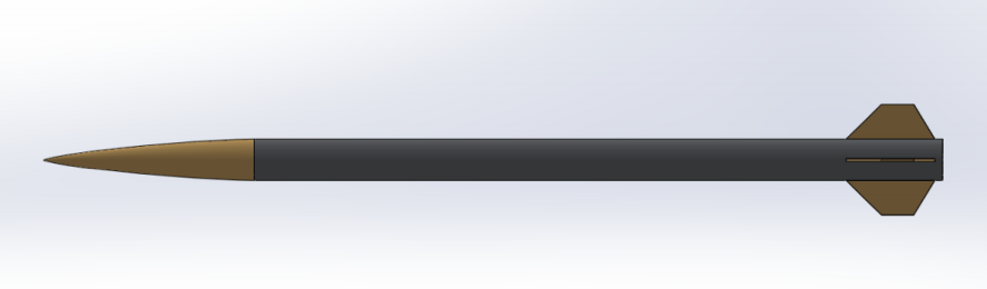
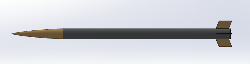
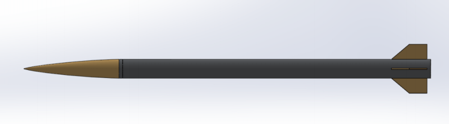
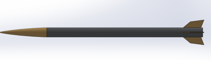
Solidworks drawings of our fin geometries are as follows:
In normal analyzes, 2D analyzes are performed as the first step. The fins that are successful in 2D analysis are considered suitable for moving to 3D analyses.
In these 2D analyzes we made, the wing that managed to reach the highest altitude was the specially designed wing, while the winglet that remained at the lowest altitude was the trapezoidal wing.
If such a choice had been made without including CFD, that is, 3D analysis, and the fin had been directly selected with these 2D analyses, a big mistake would have been made. You ask why ? Let’s examine the reason together.
Our 3D-CFD analysis results are listed below. Let’s first interpret the analyzes starting from the speed contours:

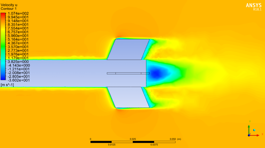


Speed contours show us whether there is a deterioration in the outflow of rockets. There is no separation of flow in any of our examples. So the fins are suitable for use. However, the first thing that catches our attention in the design of the fins is the pointed tip on the leading edge. Due to the pointed design of this tip, an acceleration has occurred on the leading edge of the winglet. This is undesirable, so that corner should be rounded in all our fins and the fins should be designed that way. However, since this is a simple analysis, we can ignore this error for now. If this error is ignored, there is no other problem with the fins.
Now it’s time for the pressure contours and our choice of suitable fins will start to take shape at this point.
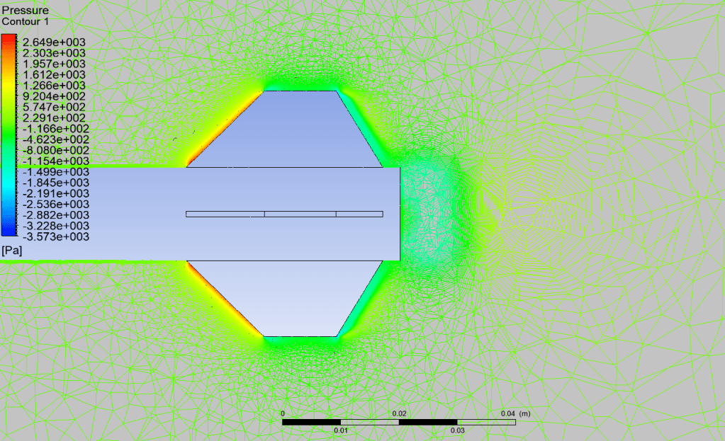

When these pressure contours are considered and the numerical pressure values are compared, it is clearly seen that the parallelogram and the specially designed fin are not suitable designs for our rocket. So why ?
Problems for parallelogram fin:
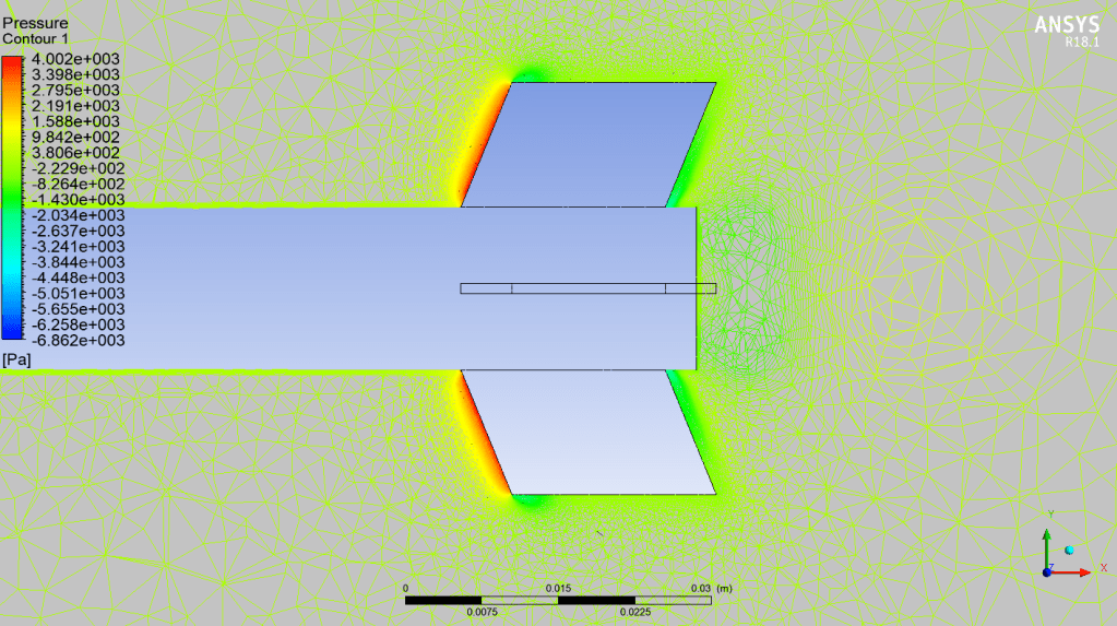
When we look at the parallelogram fin, we see a serious increase in pressure, not a decrease in pressure. We see a dark red and high numerical value pressure on the fin edge, which is short and first exposed to the flow, called the leading edge. While the pressure in other fins is less than 2.5 kPa, the pressure in this fin reaches up to 4 kPa. Moreover, this numerical value is the pressure on the reduced and modeled version of the rocket. In an analysis on real designs, this pressure difference between the other fins and the parallelogram fin will appear as a larger value. This fin type should not be preferred in case the fin is not damaged by these pressures caused by heat and strength, and against adverse situations such as crashing, exposure to loss of stability, and burning that may occur with this damage.
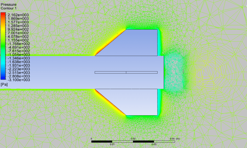
Problems for special design fin:
Although this fin type was our highest altitude wing on 2D analysis, it showed the opposite result in our aerodynamic analyzes. When the pressure contour is looked at carefully, it can be seen that there is a serious pressure drop at the rear of the fin. These negative pressures indicate that our rocket may be subject to obvious turbulence, and it is normal for it to wobble during flight. This is an undesirable situation for a stable flight. The flight of the rocket will not be healthy. Therefore, it is not a suitable design.
Upright Trapezoidal (Crooked) Fin and Its Basic Problems:
There is no problem due to pressure or flow separation in the trapezoidal blade. The design is aerodynamically appropriate. The only downside to this fin is its large surface area compared to other options. However, in addition to this size, production is also easier compared to others.
Trapezoidal Fin and Its Basic Problems:
As with the trapezoidal fin, no aerodynamic problems were observed in this fin. In addition, since the surface area of the fin is smaller than the vertical trapezoidal shape, it will also be affected by the friction force at a minimum level, so it is the design type that should be preferred for a good altitude. The only downside is that it needs a good mechanical design. As long as the production and assembly is done correctly, the abandonment of high-altitude rocket teams like us will undoubtedly be trapezoidal fin type.

In other words, trapezoidal and upright trapezoidal (crooked) shapes are suitable aerodynamically designed shapes, whereas parallelogram and special design fins are not suitable aerodynamically. To reach these conclusions; Check if there is any pressure on the vane that could cause turbulence or serious damage over the pressure contours. On the velocity contour, it should be checked whether there is separation in the flow, that is, whether the flow analysis and the flight of the assumed design are smooth.
Stay with science and knowledge.
Halit Yusuf Genç
PARS Rocket Group Aerodynamic Member
